Hardness Test Blocks
What is a Hardness Test Blocks?
Hardness testing is a testing method for determining the properties that supersede the tensile strength of a material. It is widely used to evaluate qualities such as the durability of machine parts and heat treatment. However, since durometers often assign different hardness values depending on the tester, it is extremely important to calibrate the tester using a standard to ensure the reliability of the quality of several machines in use.
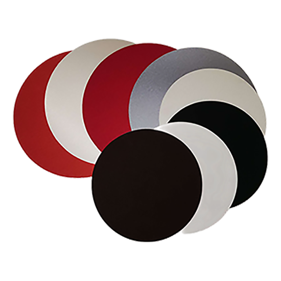
The hardness Test Block is one of the reference plates whose hardness standard values are shown as shown in the photo and is used for the calibration and control of the hardness tester

ASAHI develops and supplies various high-precision hardness standard pads using engineering qualities.
We offer the following hardness test blocks as below:
- Rockwell: Regular and Superficial scales
- Vickers: 10kgf to 30kgf
- Micro Vickers: Loads from 50gf to 1kgf
- Knoop
- Brinell: HBW5/750, HBW5/250, HBW10/500, HBW10/3000, HBW2.5/62.5, HBW5/187.5
- Shore
Rockwell Hardness Test Blocks

90HRB

30HRB
60HRC

Rockwell standard sample container
Vickers Hardness Test Blocks

Micro Vickers Test Blocks
Information of Hardness Test Blocks
Rockwell
Rockwell C
HRC 20, 25, 30, 35, 40, 45, 50, 55, 60, 62, 64
φ65 x 15 (mm)
HRC 67, 70
φ65 x 15 (mm)
Rockwell B
HRB 30, 40, 50, 60, 70, 80
φ65 x 11 (mm)
HRB 90, 95, 100
φ65 x 15 (mm)
Rockwell A
HRA 55, 60, 65, 70, 75, 80
φ65 x 15 (mm)
HRA 85
φ65 x 15 (mm)
Rockwell 15N
HR15N 70, 75, 80, 85, 90
φ65 x 15 (mm)
Rockwell 30N
HR30N 40, 45, 50, 55, 60, 65, 70, 75, 80
φ65 x 15 (mm)
HR30N 85
φ65 x 15 (mm)
Rockwell 45N
HR45N 20, 30, 40, 50, 60, 70
φ65 x 15 (mm)
Rockwell 15T
HR15T 70, 75, 80, 85
φ65 x 11 (mm)
HR15T 90
φ65 x 15 (mm)
Rockwell 30T
HR30T 30, 35, 40, 45, 50, 55, 60, 65, 70, 75
φ65 x 11 (mm)
Rockwell 30T
HR30T 80
φ65 x 15 (mm)
Rockwell 45T
HR45T 20, 30, 40, 50
φ65 x 11 (mm)
HR45T 60,70
φ65 x 15 (mm)
Rockwell E
HRE 70, 80, 90, 92, 100
φ65 x 11 (mm)
HRE 112
φ65 x 15 (mm)
Rockwell …
HRF, L, M, R, S, 15Y, and so on
φ65 x 15 (mm)
Vickers
Vickers HV10
HV(10) 100
HV(10) 200, 300, 400
φ65 x 15 (mm)
φ65 x 15 (mm)
Vickers HV30
HV(30) 500, 600, 700, 800
HV(30) 900, 950
φ65 x 15 (mm)
φ65 x 15 (mm)
Micro Vickers
Micro Vickers HMV0.05
HMV(0.05) 100
φ32 x 7 (mm)
Micro Vickers HMV0.1
HMV(0.1) 200
φ32 x 7 (mm)
Micro Vickers HMV0.2
HMV(0.2) 300, 400, 500, 600, 700
φ32 x 7 (mm)
Micro Vickers HMV0.3
HMV(0.3) 800
HMV(0.3) 900, 950
φ32 x 7 (mm)
φ32 x 7 (mm)
Brinell
Brinell HB(10/500)
HB(10/500) 100
φ115 x 18 (mm)
Brinell HB(10/3000)
HB(10/3000) 180, 200, 229, 250, 300, 350, 400, 450, 500, 550, 600
φ115 x 18 (mm)
Shore
Shore HS
HS 30, 40, 50, 60, 70, 80, 90
φ65 x 15 (mm)
Shore HS
HS 95, 100
φ65 x 15 (mm)
Knoop
Knoop
HK 100, 200, 300, 400, 500, 600, 700, 800
φ32 x 7 (mm)
Proper Indentation Spacing when using Hardness Test Blocks
When making indentations on a test block, the hardness of the material immediately surrounding an indentation will usually increase due to the residual stress and work hardening caused by the indentation process. If an indentation is made too close to the edge of a test piece, there may be insufficient material to constrain the deformation around the indentation. Both of these scenarios can lead to inaccurate hardness readings. To prevent incorrect readings, recommended spacing has been defined in the standards for each type of hardness test.
Brinell and Rockwell
According to ASTM, ISO, and JIS Standards: The distance between the centers of two adjacent indentations shall be at least three times the diameter (d) of the indentation.
The distance from the center of any indentation to an edge of the test piece shall be at least two and a half times the diameter of the indentation.

Vickers
According to ASTM Standards: The distance between two indents or an indent and the edge of the test piece shall be at least two and a half times the diagonal (dV) of the indentation.

According to ISO and JIS Standards: The distance between the centers of two indents shall be at least three times the diagonal (dV) of the indent for steel, copper, and copper alloys, and at least six times for light metals, lead, and tin, and their alloys.
The distance between the center of an indent and the edge of the test piece shall be at least two and a half times the diagonal (dV) for steel, copper, and copper alloys, and at least three times for light metals, lead, and tin, and their alloys.